- Posted on April 5th, 2022
The Conservation of Brunel’s SS Great Britain

Author: Nicola Grahamslaw, Ship’s Conservation Engineer, SS Great Britain Trust
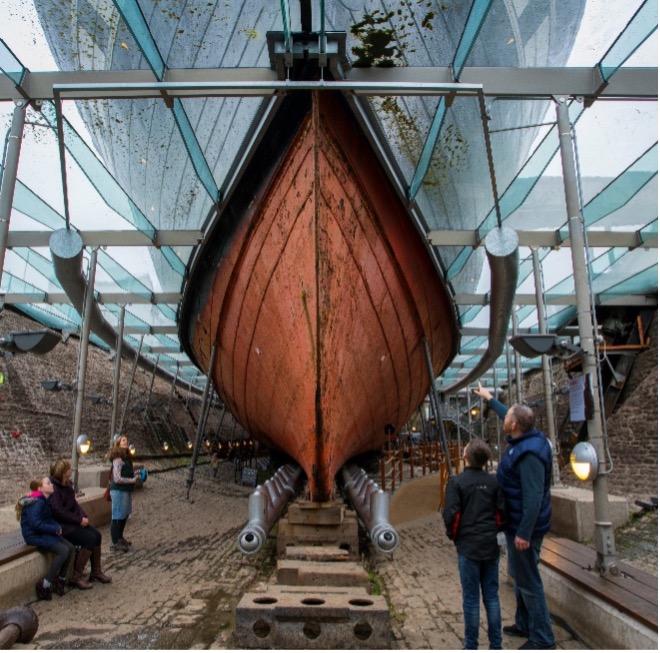
Launched in 1843, Brunel’s SS Great Britain was the first iron ocean-going ship, the first to be driven with a screw propeller, and is a technological milestone of world importance. Salvaged in 1970, the ship and dry dock in which she was constructed now operate as a museum in Bristol.
Between 1997-2005 an award-winning, first-of-its kind conservation system was developed for the ship, preserving the most vulnerable parts of the original iron by keeping the surrounding air at 20% relative humidity to stop aggressive chloride-accelerated corrosion further degrading the material. A glass “sea” at waterline level creates a seal, with two bespoke desiccant dehumidifiers treating the air inside and underneath the ship (Figure 1
In 2018 the “Ship’s Conservation Engineer” role was created, with a view to bringing whole system-level understanding and ownership of the conservation system in-house and developing a long-term sustainable conservation strategy for this unique object, leading the Trust’s ambition to become Carbon Neutral in its operations by 2030.
Operation of the dehumidification system
Each of the two dehumidifiers comprises two streams of air:
- The “supply” stream dries air by forcing it through an adsorbent desiccant, circulates the dried air around the ship or the dry dock, and then recycles it for re-drying and recirculating, mixing in fresh air if CO2 levels become too high.
- The “reactivation” stream takes in external air, heats it using natural gas then uses the hot air to remove moisture from the desiccant, exhausting the now damp air from the desiccant to the external environment. Heat exchangers recover heat from the exhaust air, pre-heating the incoming air.
The two streams are connected via the desiccant, fixed to a rotor continually moving each segment through the supply stream to extract moisture from the supply air, and then through the gas-heated reactivation stream where moisture is extracted and exhausted (Figure 8).
To control the system, humidity sensors are positioned around the ship, and the difference between the average and target relative humidity (RH) is used to control the gas supply to the reactivation heaters via a control algorithm. When the RH gets too high, more gas is added and the reactivation stream air becomes hotter, removing more moisture from the desiccant material.
The key carbon footprint contributors of this system are the gas supply providing heat to the reactivation stream, and the four fans used to circulate air through each of the two supply and reactivation streams.
An initial assessment of the system completed by the Ship’s Conservation Engineer found that the wireless sensors supplying the average ship and dry dock RH data were not providing an adequate signal for the controls to rely on.
The combination of inadequate sensor data and what appeared to be a poorly tuned control algorithm meant that the dehumidifiers were constantly cycling: requesting too much followed by too little gas, therefore repeatedly over- and under-shooting the target RH. Rectifying this was identified as a priority because during periods when the gas demand was too low, moisture was being actively introduced into the system via cold damp air in the reactivation stream, and during periods when the gas demand was too high, energy was being wasted drying the desiccant, and therefore the space, more than required (Figure 2).

Work completed prior to the Accelerator project
An application was submitted to the DCMS Wolfson Museums and Galleries Improvement Fund to migrate the obsolete Building Management System (BMS) to a newer and more user-friendly software package, and to replace the wireless sensors with wired sensors, overcoming the identified battery and communication issues. A set of portable wireless sensors was also purchased offering better signal transmission to monitor less accessible parts of the ship and dry dock, with an option to exclude the wireless data from the control system averaging and use them solely for monitoring if signal reliability became an issue.
The originally proposed Accelerator project was to use the data becoming available from these new sensors to better control the dehumidifiers, eliminate the overshooting, and develop a deeper understanding of the relationship between external weather conditions, visitor numbers and dehumidifier behaviour. This would allow further fine-tuning of the controls, for example using weather forecasting, visitor opening hours and events schedules to pre-empt changes in conditions and optimise the performance of the system.
Changing project direction, 2020-21: Fan and Desiccant Upgrades
As the project progressed, the desiccant manufacturer was consulted for advice on how best to run the equipment given the new sensors and our aspiration to reduce our energy consumption. An opportunity arose to install upgrades to the fans and heat transfer system which would give larger and quicker savings than the originally proposed smaller-scale control adjustments – potentially paying for themselves within 2-3 years. During 2021, focus therefore shifted to work supporting these upgrades, including energy payback calculations, due diligence, fundraising and staff/volunteer/public engagement activities.
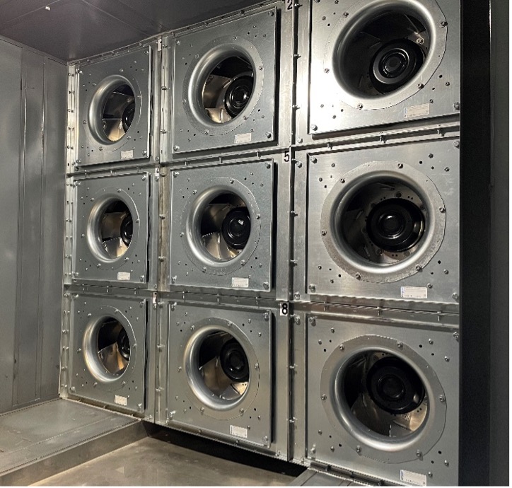
The first upgrade was to replace the belt-driven scroll fans which had been circulating air around the ship and dry dock since the dehumidifiers were first installed in 2005. The proposed solution was a “grid” of smaller modern direct-drive fans, with the drive motors situated directly inside each fan eliminating transmission losses associated with the drive belts (Figure 3 and Figure 4). The grid arrangement also provides a more even airflow across the path travelled by the dehumidified air.
The new fan grids on the ship and dry dock dehumidifiers are expected to provide an estimated saving of 140MWh per year, which equates to approximately 48 tonnes of CO2.


The second upgrade was an Energy Recovery Purge system (ERP), an additional heat recovery device in the reactivation stream of each dehumidifier
(Figure 5). This device fits straight onto the desiccant rotors, cooling the part of the desiccant moving from the reactivation stream into the supply stream and adding the recovered heat to reduce the demand on the gas burners. In addition to recycling the heat, cooling the desiccant material as it moves into the supply stream also improves its adsorption performance and reduces the load on the subsequent cooling system.

Following installation of the ERP systems, some simple changes have been made to the control algorithms to reduce the magnitude of the gas supply overshoots. Although there is still further work to be done in this area, the ERP system combined with small algorithm changes made since November 2021 are already allowing the two reactivation streams to run at more consistent and cooler temperatures (Figure 6 and Figure 7), so far giving an estimated gas saving of around 20-25% compared to the equivalent operating period between November 2020-January 2021. The estimated total annual saving for the two ERP systems is around 585MWh, which equates to approximately 173 tonnes of CO2.


Future Decarbonisation Activities: Getting to Carbon Neutral
Previous analysis on the dehumidifier systems conducted in 2010 had concluded that moving away from gas for heating was not feasible for two reasons: Firstly, because heat was required by the system at a higher temperature than could be easily provided by hot water. Secondly, transferring heat to the reactivation air without gas would require obstructing the flow with a large surface area heat exchanger, requiring a more powerful fan to drive the air through the system to be heated. Direct heat from gas was deemed the only feasible option because heat could easily be supplied at a high temperature and burning the gas directly in the reactivation air stream meant that the air could be heated directly without restricting the flow with a radiator or heat exchanger.
The work completed as part of the 2020/2021 accelerator project has the potential to remove both barriers to decarbonisation identified in the 2010 analysis:
- The control algorithm adjustments combined with the ERP system mean that the reactivation streams are operating with heat supplied at a lower and more consistent temperature, which could more easily be delivered via a hot water system heated using a non fossil fuel source.
- The technology now installed on the supply stream fans, if also installed on the reactivation stream fans could provide more fan power for the same amount of electrical power (as opposed to the same amount of fan power for less electrical power as installed in the supply streams), allowing air to flow through an additional heat exchanger. The types of fans installed in our supply streams are not currently suitable for the reactivation streams because the materials are not able to withstand the high moisture levels in the reactivation exhaust air, but the manufacturer is currently developing a product using different materials to overcome this limitation.
In addition to providing the direct emissions reductions, this project has therefore taken the conservation system on the SS Great Britain from being fully reliant on natural gas, to becoming a candidate for future electrification. The expert support time is currently being used to set out some possible options to achieve carbon neutral operation in the future, given the shift in operating conditions achieved during this project.
Efforts are also underway to address and reduce the SS Great Britain Trust’s scope 3 emissions, recognising that these are much less significant than Scopes 1 and 2 but important nonetheless. A sustainable procurement policy is being developed along with education and incentives for staff, volunteers and visitors to reduce the Carbon footprint of their activities working with and visiting the ship.
